Quality assurance and testing of Printed Circuit Boards (PCBs) is a critical part of the development process. From prototype to production, it’s essential that PCBs are tested for functionality and reliability before being put into use.
This article explores best practices and protocols in PCB testing and quality assurance, providing an overview of the most common methods used for ensuring high-quality results at every stage. It will discuss various aspects such as design considerations, temperature control, component selection, test equipment setup, data analysis techniques, and more – all designed to help you get your products from concept to completion with confidence.
Proper Testing and Documentation Procedures
Proper testing and documentation procedures are essential to ensure the best possible results in PCB testing and quality assurance. Testing should be conducted regularly, as even small discrepancies can have a significant impact on the performance of the circuit board.
Tests should also be properly documented so that any changes or improvements made can be tracked over time. It is important to make sure that all tests are performed according to industry standards and with accuracy and precision.
Additionally, test documentation must include detailed information about the conditions under which tests were run, materials used for testing, equipment used for measurements, readings from each test run, etc. This will help teams understand what works well and what needs improvement to optimize future circuit board products.
Furthermore, all members of the team must follow established protocols when conducting tests to maintain consistency across all projects produced by an organization. Properly implemented testing procedures will help organizations achieve their goals of producing high-quality circuit boards with increased efficiency while reducing costs associated with product development failures due to failing components or design mistakes.
Establishing Quality Assurance Standards

The establishment of quality assurance standards is key to ensuring the accuracy and reliability of PCB testing and quality assurance. High-quality components require stringent tests to guarantee their performance, safety, and durability.
To ensure that all test results are reliable, companies must develop a set of protocols for each step in the process. This includes establishing criteria for inspection, quantifying acceptable levels of performance or failure rates, setting up repeatability tests on every batch produced, and creating an audit system to monitor progress.
Quality assurance protocols should also be regularly reviewed to identify areas where improvements can be made and processes refined over time. Companies should strive for a balance between cost efficiency and assuring the highest possible level of testing accuracy.
By adhering to these best practices, organizations can ensure that their products meet rigorous standards while providing maximum value at minimum cost.
Identifying Defects During Inspection Processes
Identifying defects during inspection processes is an essential step in the PCB testing and quality assurance process. To ensure that boards are working as intended, inspectors need to have a comprehensive understanding of what constitutes a defect and how best to identify it.
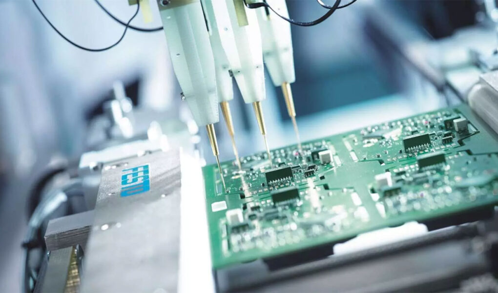
Common techniques used in identifying defects include visual inspections, x-ray imaging, optical inspection, surface mount component measurements, and automated optical inspection (AOI). Visual inspections can be used to detect issues such as shorts or open on the board’s circuit paths; however, they cannot account for whether components are correctly placed or soldered properly.
X-ray imaging allows inspectors to view internal layers of the board with greater accuracy than human sight alone could provide while also being able to determine if components are correctly placed and soldered. Optical inspection systems use cameras to measure features such as solder joint heights or coplanarity of parts.
Surface mount component measurements allow inspectors to take precise measurements of key parameters like components lead widths which can help detect potential problems before mass production begins. Finally, Automated Optical Inspection (AOI) uses special software algorithms alongside computer vision technology for more accurate defect detection rates than humans can achieve manually.
By utilizing these various techniques together during the PCB testing process, manufacturers can better identify any potential issues before moving forward with their product into the production stages.
Troubleshooting Techniques for PCB Components
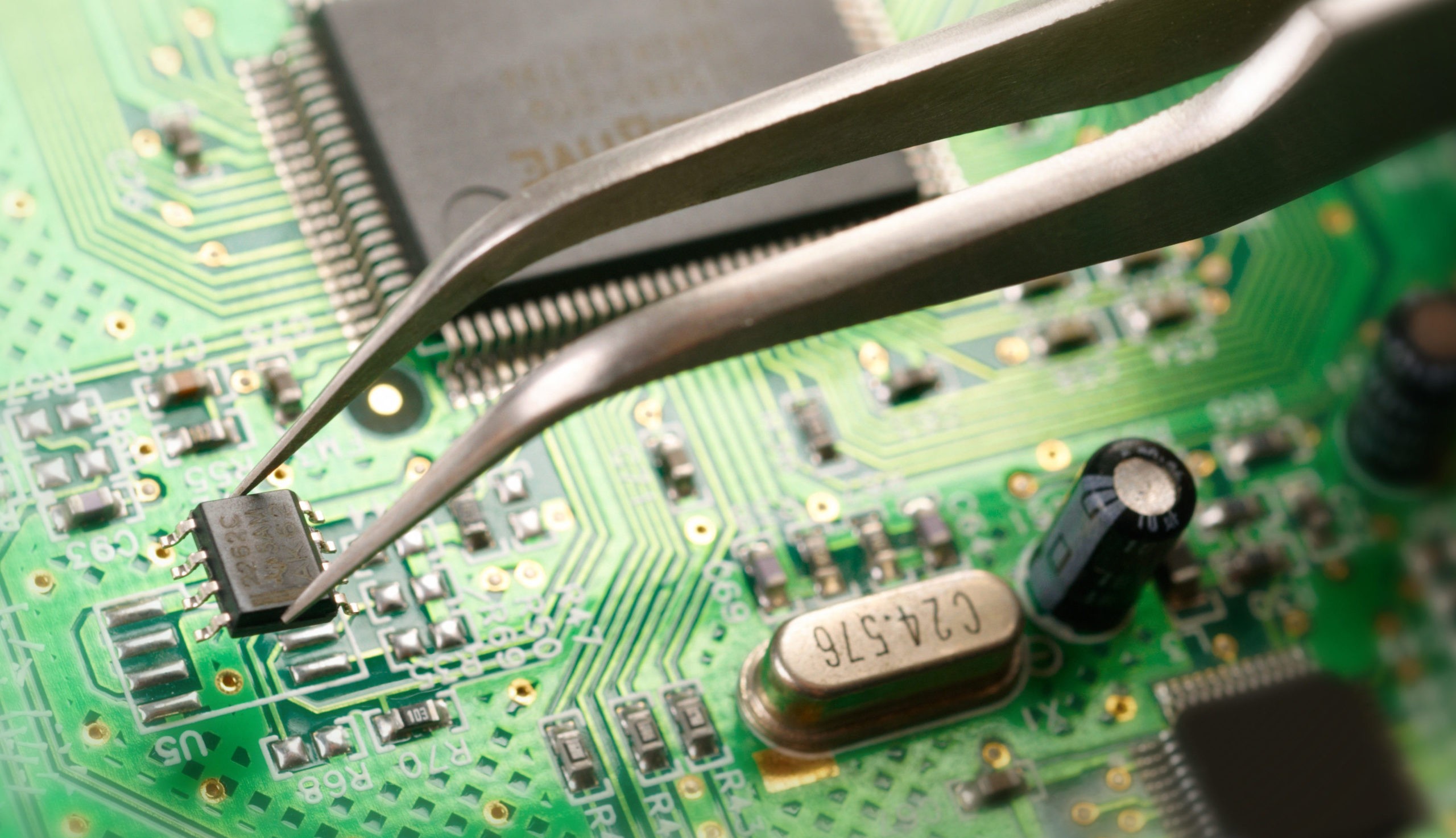
When troubleshooting PCB components, it is important to consider both the actual component and its surrounding environment. Different types of testing should be employed to determine whether the component is functioning properly or requires replacement.
Visual inspection can be used to identify any physical damage that may have occurred due to improper handling or installation. Additionally, electrical tests such as continuity checks, voltage level measurements, and insulation resistance measurements can help detect problems with wiring connections or short circuits in the circuit board. Further diagnostic steps could include load testing, functional tests using a test jig, and most importantly – identification of the root cause before replacing defective components.
It is also recommended that preventative measures are taken while assembling PCBs which include proper component orientation for heat dissipation; avoiding overloading traces with too much current; ensuring that all soldering joints are secure; regularly inspecting boards for signs of corrosion due to environmental exposure; and following established design rules when creating new components on a board so as not to create interference between different parts of the same circuit board. With these best practices in mind, troubleshooting potential issues with PCBs becomes easier and more efficient than ever before!
Evaluating System Performance Requirements
Evaluating system performance requirements for quality assurance in PCB testing is an essential part of the best practices and protocols. When assessing a product, it is important to consider factors such as accuracy, reliability, speed of operation, and cost-effectiveness.
Accuracy determines how exact the results are compared to what was expected, while reliability takes into account whether or not there were any errors during the process. Speed of operation can be determined by calculating the time required for all necessary tests to be completed successfully and at what rate new tests can be added or updated.
Cost-effectiveness ties into these other measures by taking into account both equipment costs and labor costs associated with each test or protocol run. By understanding these different factors when evaluating a system’s performance requirements one will have a better idea of how well they meet their intended purpose in terms of quality assurance within PCB testing.
Conclusion

PCB testing is an essential part of the process to ensure that a printed circuit board meets the requirements and specifications for its intended purpose. Quality assurance protocols within PCB testing guarantee that all components are in working order, providing reliable functionality.
Best practices for PCB testing involve utilizing advanced equipment with multiple levels of inspections to identify any issues or defects in the product before it reaches end users. By following these best practices and quality assurance protocols, businesses can make sure their printed circuit boards meet standards while also saving money on production costs due to fewer returns and less reworking of components.